
Featured Collection
Your cart
Featured Collection

PEAK SURGICALS
SKU:PS-OP-5130
Couldn't load pickup availability


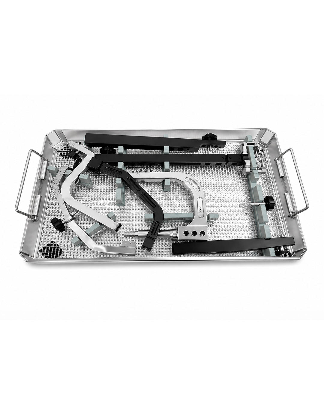
Instrument Set For Retrograde Femoral Nail, SKU PS-OP-5130, is a 69-piece reusable German-forged stainless steel orthopedic system for distal femoral entry, canal preparation, nail insertion, guided locking, and extraction. The PS-041 configuration includes threaded guide wires, tissue protector, locking-screw depth gauge, entry drill and wire guides, Ø13.5 mm entry reamer and four-cornered awl, guide handle, distal and proximal aiming devices with arms, connectors and bolts, stabilizing guides, rods and spacers, Ø9.5–12 mm lateral stabilizers, Allen wrench, handle impactor, rod drill, hammer guide, extraction screw, trocar nail, position rod, Ø9–13 mm reamer heads, quick-coupling T-handle, reducer, olive guide wire, flexible reamer shaft, outer and cannulated sleeves, long trocar, Ø4.0 mm drills with stopper, locating pins, lateral-cortex reamer, locking-screw hex wrenches with threaded trocars, combined hammer and wrench, impactor pin wrench, screw tray, and container. Orthopedic trauma surgeons use the set for retrograde intramedullary fixation of selected distal-third and diaphyseal femoral fractures, including compatible periprosthetic fractures proximal to a knee component. It supports intercondylar entry, fracture reduction, sequential reaming, controlled nail seating, multiplanar screw placement, and hardware removal in trauma theatres and tertiary orthopedic centers.
The retrograde workflow begins at the intercondylar notch, where the threaded guide wire establishes a fixed reference under AP and lateral imaging. The tissue protector creates a guarded corridor through the knee approach, while the 17/14 mm drill guide and Ø13.5 mm wire guide center the entry path. The matching reamer opens the distal femoral canal; the four-cornered pointed awl provides a manually controlled alternative for initial osseous access. An olive-tipped 1000 mm wire then maintains the medullary trajectory across the reduced fracture. Interchangeable Ø9–13 mm heads connect to the flexible shaft, allowing progressive canal enlargement in 0.5 mm increments. The guide handle couples rigidly to the nail and accepts the impactor for axial advancement. Proximal and distal targeting assemblies mount through arms, connector guides, and locking bolts so their apertures reproduce the implant’s screw-hole geometry. Stabilizing rods, guides, and spacers brace this construct against bending, while size-specific lateral rods correspond to the operative nail diameter. At each locking site, the outer sleeve protects soft tissue, the cannulated sleeve centers the Ø4.0 mm drill, the stopper limits advancement, and the depth gauge determines the 5.0 mm screw length. Hexagonal wrenches transmit insertion torque; threaded trocars retain alignment through the deep working channel.
For a distal-third or femoral shaft fracture selected for retrograde fixation, the patient is positioned on a radiolucent table with the knee flexed for intercondylar access. Under fluoroscopy, the threaded wire is centered in the notch on the AP view and aligned with the distal femoral canal on the lateral projection. The tissue protector, entry guide, Ø13.5 mm reamer, or pointed awl establishes the portal without allowing the rotating cutter to contact adjacent soft tissue. The olive wire is passed across the reduction into the proximal fragment; the reducer assists correction when the wire cannot traverse displaced cortices directly. Sequential Ø9–13 mm heads prepare the canal over the flexible shaft according to the planned implant diameter. The nail is attached to the guide handle, advanced with the impactor or combined hammer, and seated below the articular surface while depth is monitored. The targeting frame is secured with its connector, arms, bolts, stabilizing rods, and diameter-matched lateral support. Sleeves and trocars establish each protected locking corridor; the Ø4.0 mm drills create bicortical paths, the gauge selects 5.0 mm screw length, and the hex wrench completes insertion. Distal and proximal locking order follows the implant technique and reduction objective. Final biplanar imaging confirms nail depth, femoral length, rotation, fracture alignment, and screw position.
PS-041.001 supplies two Ø3.2 × 400 mm threaded wires with 15 mm threaded tips for entry-point fixation. Codes .019, .025, .031, and .037 form the 17/14 mm guide, Ø13.5 mm wire guide, reamer, and pointed-awl entry group, protected by .007. The aiming assembly comprises .043, .049, .055, .061, .067, .073, two .079 bolts, .103, .109, and .151; .085, .091, .097, .115, .121, .127, .133, .139, and .145 stabilize that frame. Lateral rods Ø9.5, 10, 11, and 12 mm are selected to match the corresponding nail body. Reamer heads .199 through .247 cover Ø9, 9.5, 10, 10.5, 11, 11.5, 12, 12.5, and 13 mm and run on the .271 flexible shaft over the .265 olive wire using the .253 T-handle. The .277 outer sleeves, .283 drill sleeves, .289 trocar, three .295 drills, .301 stopper, .307 locating pins, and .313 lateral-cortex reamer prepare locking paths. The .013 gauge sizes 5.0 mm screws; two .319 hex wrenches and two .325 threaded trocars control their insertion. Codes .157, .163, .169, .175, .181, .187, .193, .259, .331, .337, and .343 provide assembly, impaction, extraction, reduction, and adjustment functions. The .349 tray and .355 container organize screws and all instrumentation.
German-forged stainless steel gives the long guide elements, drill sleeves, reamer heads, couplings, and aiming components the rigidity needed to preserve coaxial alignment under manual and impact loads. A satin, non-reflective finish reduces glare under operating lights and permits inspection of cutting edges, threads, locating surfaces, and laser markings. After use, gross soil should be removed before blood and marrow dry inside cannulations or reamer flutes. Staff disassemble the targeting frame, detach each quick-coupling component, flush every sleeve and flexible-shaft interface, brush threaded bores, rinse with treated water, and dry completely. Reamer heads, drill bits, guide wires, trocars, stabilizing rods, and screw-retaining tips require magnified inspection for wear, bending, dullness, or damaged threads. Components are reconciled against the 60 coded line items, secured in the PS-041.349 screw tray and PS-041.355 container, then steam autoclaved through the facility’s validated cycle under the manufacturer’s reprocessing instructions. CE marking supports applicable European conformity documentation, while ISO 13485 identifies the quality-management framework governing manufacture, inspection, traceability, and set assembly. FDA-compliant procurement concerns registration, listing, labeling, and device records relevant to United States supply rather than an individual approval claim for each manual tool. Commercial terms include a one-year warranty, one-set MOQ, OEM or private-label configuration, and return-and-replacement service.
| Code | PS-041 Instrument Set For Retrograde Femoral Nail | Units |
|---|---|---|
| PS-041.001 | Threaded Guide Wire Ø3.2 mm × Thread Length 15 mm × Length 400 mm | 2 |
| PS-041.007 | Tissue Protector | 1 |
| PS-041.013 | Depth Gauge for 5.0 mm Locking Screw for Retrograde Femoral Nail, up to 120 mm | 1 |
| PS-041.019 | Drill Guide 17/14 mm for Entry Reamer and Wire Guide | 1 |
| PS-041.025 | Entry Wire Guide Ø13.5 mm | 1 |
| PS-041.031 | Entry Reamer Ø13.5 mm | 1 |
| PS-041.037 | Four-Cornered Pointed Awl Ø13.5 mm | 1 |
| PS-041.043 | Guide Handle | 1 |
| PS-041.049 | Distal Aiming Device | 1 |
| PS-041.055 | Distal Arm | 1 |
| PS-041.061 | Distal Aiming Arm | 1 |
| PS-041.067 | Aiming Connector Guide | 1 |
| PS-041.073 | Proximal Aiming Device | 1 |
| PS-041.079 | Aiming Device Bolt | 2 |
| PS-041.085 | Stabilizing Rod Guide | 1 |
| PS-041.091 | Stabilizing Rod with Quick-Coupling End | 1 |
| PS-041.097 | Stabilizing Spacer | 1 |
| PS-041.103 | Proximal Arm | 1 |
| PS-041.109 | Locking Bolt for Proximal Arm | 1 |
| PS-041.115 | Rod with Thread Guide 10/7.8 mm | 1 |
| PS-041.121 | Threaded Lateral Stabilizing Rod with Quick-Coupling End Ø9.5 mm | 1 |
| PS-041.127 | Threaded Lateral Stabilizing Rod with Quick-Coupling End Ø10 mm | 1 |
| PS-041.133 | Threaded Lateral Stabilizing Rod with Quick-Coupling End Ø11 mm | 1 |
| PS-041.139 | Threaded Lateral Stabilizing Rod with Quick-Coupling End Ø12 mm | 1 |
| PS-041.145 | Rod with Thread Spacer | 1 |
| PS-041.151 | Locking Bolt for Guide Handle | 1 |
| PS-041.157 | Allen Wrench, Hex 5.0 mm | 1 |
| PS-041.163 | Impactor for Guide Handle | 1 |
| PS-041.169 | Drill for Stabilizing Rod with Quick-Coupling End | 1 |
| PS-041.175 | Hammer Guide Ø7.9 mm × Length 280 mm | 1 |
| PS-041.181 | Extraction Screw for Retrograde Nail | 1 |
| PS-041.187 | Trocar Nail Ø3 mm | 1 |
| PS-041.193 | Position Rod Ø3.8 mm × Length 260 mm | 1 |
| PS-041.199 | Reamer Head Ø9 mm | 1 |
| PS-041.205 | Reamer Head Ø9.5 mm | 1 |
| PS-041.211 | Reamer Head Ø10 mm | 1 |
| PS-041.217 | Reamer Head Ø10.5 mm | 1 |
| PS-041.223 | Reamer Head Ø11 mm | 1 |
| PS-041.229 | Reamer Head Ø11.5 mm | 1 |
| PS-041.235 | Reamer Head Ø12 mm | 1 |
| PS-041.241 | Reamer Head Ø12.5 mm | 1 |
| PS-041.247 | Reamer Head Ø13 mm | 1 |
| PS-041.253 | T-Handle with Quick Coupling | 1 |
| PS-041.259 | Reducer | 1 |
| PS-041.265 | Guide Wire with Olive Ø2.5 mm × Length 1000 mm × Olive Ø3.8 mm | 1 |
| PS-041.271 | Flexible Reamer Shaft | 1 |
| PS-041.277 | Outer Sleeve 10/8 mm | 2 |
| PS-041.283 | Cannulated Sleeve for Drill Bit 8/4 mm | 2 |
| PS-041.289 | Long Trocar Ø4.0 mm × Length 205 mm | 1 |
| PS-041.295 | Drill Bit, Plain Shank/Jacobs Chuck End Ø4.0 mm × Length 320 mm | 3 |
| PS-041.301 | Stopper for Drill Bit Ø4.0 mm | 1 |
| PS-041.307 | Locating Pin Ø4.0 mm × Length 320 mm | 2 |
| PS-041.313 | Reamer for Lateral Cortex with Quick-Coupling End | 1 |
| PS-041.319 | Hexagonal Wrench for 5.0 mm Locking Screw, Hex 4.5 mm | 2 |
| PS-041.325 | Threaded Trocar for Hexagonal Wrench Ø2.0 mm × Thread 4 mm × Length 267 mm | 2 |
| PS-041.331 | Combined Hammer | 1 |
| PS-041.337 | Combined Wrench 11 mm | 1 |
| PS-041.343 | L-Handle Pin Wrench Ø4.45 mm for Impactor | 1 |
| PS-041.349 | Screw Tray for Retrograde Locking Screws | 1 |
| PS-041.355 | Container for Retrograde Nail Instrument Set | 1 |
| Specification | Product Data |
|---|---|
| SKU | PS-OP-5130 |
| Product Name | Instrument Set For Retrograde Femoral Nail |
| Price | $1,156.06 USD |
| Size/Gauge Variants | Ø9–13 mm reamer heads; Ø13.5 mm entry instruments; Ø9.5, 10, 11, and 12 mm stabilizing rods; Ø4.0 mm locking drills |
| Instrument Category | Retrograde femoral intramedullary nail instrumentation |
| Procedure | Retrograde nailing of selected distal and diaphyseal femoral fractures |
| Material | German-forged stainless steel |
| Finish | Satin, non-reflective surgical finish |
| Sterilization | Reusable and steam-autoclavable after validated cleaning and inspection |
| Instrument Classification | Reusable manual orthopedic implant instrumentation set |
| Reusable | Yes |
| Certifications | CE marked; ISO 13485 quality-management system; FDA-compliant procurement documentation |
| Warranty | 1 year |
| MOQ | 1 set |
| OEM / Custom Orders | Available for compatible set configuration and private labeling |
| After-Sale Service | Return and replacement support |
How does a retrograde femoral nail set differ from an antegrade femoral nail instrument set?
The Instrument Set For Retrograde Femoral Nail establishes its entry portal through the intercondylar notch and advances the implant from distal to proximal. An antegrade femoral nail set enters through the greater trochanter or piriformis-region start point and advances toward the distal femur. Retrograde entry therefore requires knee-level tissue protection, a distal femoral entry reamer, and targeting geometry referenced from the nail’s distal insertion end. Antegrade sets use proximal-femoral entry sleeves, opening reamers, and targeting arms shaped around trochanteric anatomy. The two systems also position their proximal and distal locking apertures differently relative to the insertion handle. Instrument choice must follow the specific implant family, approach, nail diameter, fracture level, and operative technique.
How are the Ø9–13 mm reamers and Ø9.5–12 mm stabilizing rods selected?
The Instrument Set For Retrograde Femoral Nail provides reamer heads in 0.5 mm increments from Ø9 to Ø13 mm for progressive preparation of the femoral medullary canal. The surgeon selects the starting head according to canal access and advances sequentially toward the diameter required by the planned nail. The Ø13.5 mm entry reamer prepares the wider distal portal at the intercondylar notch and is not the same as the canal-sizing sequence. Lateral stabilizing rods in Ø9.5, 10, 11, and 12 mm correspond to compatible nail-body diameters and brace the aiming construct. Selection considers preoperative canal measurements, distal femoral geometry, fracture pattern, implant dimensions, and resistance encountered during reaming. Final choices follow the nail manufacturer’s technique and are checked under biplanar fluoroscopy.
What do CE, ISO 13485, and FDA-compliant procurement mean for this product?
The Instrument Set For Retrograde Femoral Nail is supplied within Peak Surgicals’ CE-marked framework for applicable European conformity requirements. ISO 13485 identifies the medical-device quality-management system governing controlled manufacture, inspection, traceability, and set assembly. FDA-compliant procurement concerns manufacturer registration, device listing, labeling, and documentation relevant to United States distribution. It does not mean that every reusable manual instrument has an individual FDA premarket approval decision. Hospital procurement teams should match the certificate holder, SKU, product identity, intended market, and document validity during vendor qualification. Distributors can request the corresponding files for tenders, import documentation, and OEM supply.
How does the aiming and stabilization mechanism control locking-screw placement?
The guide handle couples to the nail and provides the reference interface for proximal and distal aiming devices. Connector guides, arms, and locking bolts create a rigid geometric relationship between the external frame and the nail holes. Stabilizing rods and spacers limit deflection of the frame during sleeve placement and drilling. A diameter-matched lateral rod supports the construct according to the selected implant body. The outer sleeve rests against bone while the 8/4 mm cannulated sleeve centers the Ø4.0 mm drill and protects the working corridor. After drilling, the depth gauge selects the 5.0 mm screw length and the hex wrench advances the locking screw through the established path.
How should procurement and sterile-processing teams manage this 69-piece set?
The Instrument Set For Retrograde Femoral Nail contains 60 coded line items representing 69 individual pieces, including duplicate wires, bolts, sleeves, drills, pins, wrenches, trocars, tray, and container. Staff should reconcile every code and quantity before the set enters the operating room. Cleaning must reach reamer flutes, flexible-shaft junctions, sleeves, threaded rods, targeting-arm connections, drill stops, and screw-retaining trocars. After drying, personnel inspect guide wires and drills for straightness, reamer heads for sharpness, threads for damage, and aiming components for secure assembly. The instruments are arranged in the PS-041.349 screw tray and PS-041.355 container before the facility’s validated steam cycle. Procurement records should retain the implant compatibility statement, SKU, warranty, conformity documents, OEM configuration, and return-and-replacement terms.


